There is a multitude of metrics that manufacturers have to balance when working through the design process for conformal cooling applications. From the uniformity of the steel temperature across the mold stack up to how efficient the cooling process is, it’s critical to evaluate all components. However, the core is often the most vital.
If you’re interested in learning more about the design process, Anova Innovations, a leading company specializing in 3D steel printed steel inserts for injection molds and the supporting simulation services, looks at four different cores and works through how a manufacturer would decide on the best option.
The Objective of a New Design
In this case study, a plastic parts manufacturer was looking to upgrade a traditional mold for pharmaceutical pill bottles. This mold ran with a simple bubbler, a basic straight-line water cooling channel.
With a new, non-conventional design, the objective was to improve the cooling capabilities of a core that goes into a production stack mold. There are several benefits to improving the cooling capabilities of a mold, including, but not limited to a(n):
- Reduction in cycle time
- Improvement in part quality
- Increase in productivity
- Better ability to use bioplastics
Whether part makers are interested in the profit improvements of boosted productivity or the ability to meet consumer demands with bioplastics, comprehensive testing during the design process is critical.
The Molds in Consideration
Anova evaluated four designs through a simulation process:
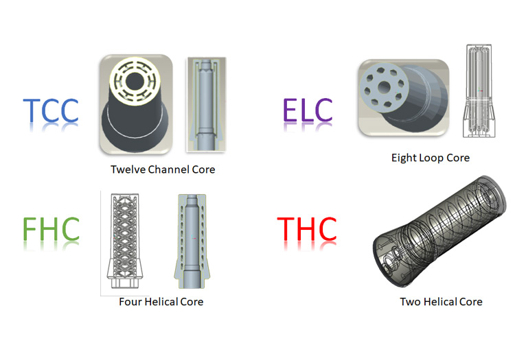
- Design 1: 12 Channel Core (TCC): This core has six primary cooling channels that are set up in a parallel system. This design forces all the water that enters the core to be split between six cooling circuits. Put simply, there are six entry points and six exit points.
- Design 2: Four Helix Core (FHC): This core has four helix-shaped channels. It splits the water into four directions during the cooling process.
- Design 3: Eight Loop Core (ELC): This core has two parallel circuits. It has one inlet that feeds two circuits, one that feeds around each side of the core. There are eight total loops—four loops per side.
- Design 4: Two Helix Core (THC): This core has two helical circuits, one in and one out. There is also a parallel circuit right at the top of the core.
When looking at a cooling design, there are a few fundamental principles you need to keep in mind:
- Temperature should be kept as uniform as possible.
- Cooling efficiency needs to be a top priority.
- The stress in the core needs to be managed to avoid fatigue cracking.
12 Channel Core (TCC)
While evaluating the first design, we quickly realized that to reach the target Reynolds number, we would need a significant amount of coolant flow through each channel. Each parallel channel would require 1.21 gallons per minute (GPM) using 60-degree Fahrenheit water. Therefore, each core would require 7.26 GPM.
| Maximum Stress | 390 Mpa/56,158 psi |
|---|---|
| GPM per Core | 7.26 |
| Average Heat Transfer Rate | 582.65 watts |
Four Helix Core (FHC)
Based on the channel geometry of the FHC, parts manufacturers would need to run 1 GPM per channel (4 GPM for the core) with 60-degree Fahrenheit water.
| Maximum Stress | 490 Mpa/70,615 psi |
|---|---|
| GPM per Core | 4.0 |
| Average Heat Transfer Rate | 582.8 watts |
Eight Loop Core (ELC)
The ELC design requires .75 GPM per channel with 60-degree Fahrenheit water and 1.5 GPM for the entire core.
| Maximum Stress | 174 Mpa/25,230 psi |
|---|---|
| GPM per Core | 1.5 |
| Average Heat Transfer Rate | 561.90 watts |
Two Helix Core (THC)
The THC design requires 0.9 GPM per channel and core with 60-degree Fahrenheit water.
| Maximum Stress | 264 Mpa/38,280 psi |
|---|---|
| GPM per Core | 0.9 GPM |
| Average Heat Transfer Rate | 574.83 watts |
*Reynolds Number is an engineering term that determines that type of flow as either laminar or turbulent. The heat transfer capability of a molds cooling system is improved with turbulent flow.
The Results of These Designs
These conformal cooling cores showed incredible improvements in productivity, cost savings, and statistically capable parts. If you’re interested in learning more about the results of Anova’s designs, sign up for our newsletter to receive part two of this case study.